-
-
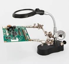
Product Type: Helping Hand Magnifier with LED & Soldering Stand
-
Magnification: 3.5X (main lens), 12X (auxiliary lens)
-
Light Source: Built-in LED light
-
Clips: Adjustable alligator helping hands
-
Stand: Soldering iron holder + stable weighted base
-
Material: Metal + optical glass + ABS
-
Applications: Electronics repair, soldering, PCB work, jewelry making, crafting
-
Power Supply: Battery-operated LED (varies by model)
20 day deliveryQuick View
Wishlist
Compare
Add to cartSold: 0Available: 6-
Product Type: Helping Hand Magnifier with LED & Soldering Stand
-
Magnification: 3.5X (main lens), 12X (auxiliary lens)
-
Light Source: Built-in LED light
-
Clips: Adjustable alligator helping hands
-
Stand: Soldering iron holder + stable weighted base
-
Material: Metal + optical glass + ABS
-
Applications: Electronics repair, soldering, PCB work, jewelry making, crafting
-
Power Supply: Battery-operated LED (varies by model)
20 day delivery -
-
-
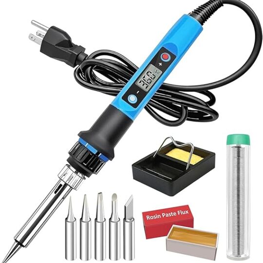
Type: High Power Electric Soldering Iron
-
Input Voltage: 220V
-
Power Range: 30W / 70W (dual power adjustable)
-
Heating Element: Quick heat-up ceramic core
-
Handle: Heat-resistant ergonomic grip
-
Applications: PCB soldering, motherboard repair, jumper wire, DIY projects
Quick View
Wishlist
Compare
Add to cart-
Type: High Power Electric Soldering Iron
-
Input Voltage: 220V
-
Power Range: 30W / 70W (dual power adjustable)
-
Heating Element: Quick heat-up ceramic core
-
Handle: Heat-resistant ergonomic grip
-
Applications: PCB soldering, motherboard repair, jumper wire, DIY projects
-
-
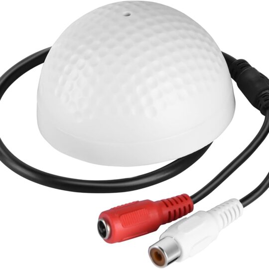
Product Configuration
-
Check Compatibility: Ensure your camera/DVR has an audio input port (e.g., 3.5mm jack).
-
Connect Microphone: Plug the mic into the camera’s audio input port.
-
Power On: If required, connect the mic to a DC power source (e.g., 12V adapter).
-
Camera Settings: Enable audio recording in the camera/DVR settings (via app or menu).
-
Test Audio: Verify sound quality through the camera’s live feed or playback.
Quick View
Wishlist
Compare
Add to cartProduct Configuration
-
Check Compatibility: Ensure your camera/DVR has an audio input port (e.g., 3.5mm jack).
-
Connect Microphone: Plug the mic into the camera’s audio input port.
-
Power On: If required, connect the mic to a DC power source (e.g., 12V adapter).
-
Camera Settings: Enable audio recording in the camera/DVR settings (via app or menu).
-
Test Audio: Verify sound quality through the camera’s live feed or playback.
-
-
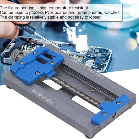
Product Configuration
This is a mechanical tool. Its “configuration” involves adjusting it to fit your specific workpiece:
-
Placement: Position the holder on a stable, flat work surface close to your soldering station.
-
Adjust the Arms:
-
Loosen the knobs or bolts on the holder’s articulated arms.
-
Position the arms so the clips are near the edge of the PCB you want to hold.
-
-
Secure the PCB:
-
Use the clips to grip the PCB on its edges, ideally on a non-critical area with no components or traces.
-
For large boards: Use two clips on opposite sides.
-
For small boards: Use two clips on one side or angle them to grip securely.
-
Quick View
Wishlist
Compare
Add to cartProduct Configuration
This is a mechanical tool. Its “configuration” involves adjusting it to fit your specific workpiece:
-
Placement: Position the holder on a stable, flat work surface close to your soldering station.
-
Adjust the Arms:
-
Loosen the knobs or bolts on the holder’s articulated arms.
-
Position the arms so the clips are near the edge of the PCB you want to hold.
-
-
Secure the PCB:
-
Use the clips to grip the PCB on its edges, ideally on a non-critical area with no components or traces.
-
For large boards: Use two clips on opposite sides.
-
For small boards: Use two clips on one side or angle them to grip securely.
-
-
-
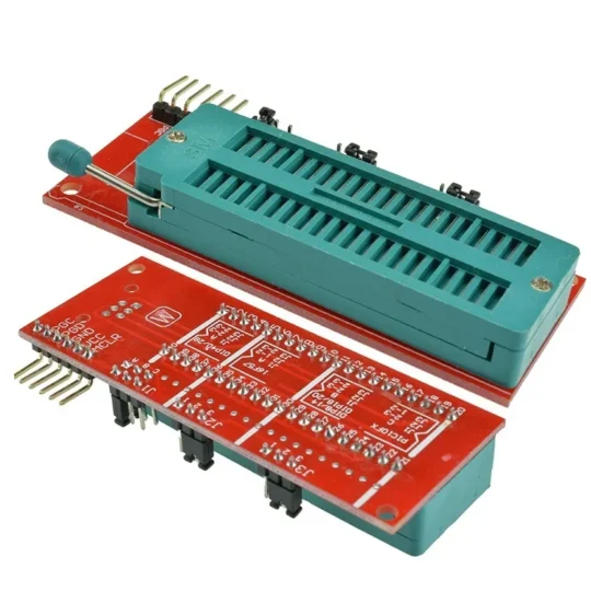
This adapter is not “configured” via software but rather through physical wiring. Here is how to set it up:
-
Identify Your PIC Chip: Find the exact part number of your PIC microcontroller (e.g., PIC16F877A, PIC18F46K22, etc.).
-
Locate the ICSP Pins: Consult the chip’s datasheet to find which physical pins are used for the five ICSP signals:
-
VPP/MCLR: Programming Voltage (Usually pin #1)
-
VDD: Positive Supply Voltage
-
VSS: Ground
-
PGC: Serial Programming Clock
-
PGD: Serial Programming Data
-
-
Configure the ZMorph Socket: Using the pinout diagram that comes with the adapter (or a standard ZMorph chart found online), place jumper wires on the board to connect the ICSP header pins (from your programmer) to the specific socket pins that correspond to the target chip’s VPP, VDD, VSS, PGC, and PGD.
-
Connect the Programmer: Plug your PICkit 3 (or other supported programmer) into the 6-pin ICSP header on the adapter board via a standard RJ-11 cable (for PICkit) or a ribbon cable.
-
Insert the Chip: Carefully place the PIC chip into the configured ZIF socket and lock it in place.
-
Power the Board:
-
Option A (Self-Powered): The board can often be powered directly from the programmer (via the
VDDpin from the ICSP header). Ensure your programmer can supply enough current. -
Option B (External Power): For chips requiring more power, provide an external regulated +5V (or the chip’s required voltage) to the
VEXTandGNDterminals on the board. You must ensure the external power supply’s ground (GND) is connected to the programmer’s ground.
-
-
Program: Use Microchip’s MPLAB X IDE or the standalone software to program the chip as you normally would.
Quick View
Wishlist
Compare
Add to cartThis adapter is not “configured” via software but rather through physical wiring. Here is how to set it up:
-
Identify Your PIC Chip: Find the exact part number of your PIC microcontroller (e.g., PIC16F877A, PIC18F46K22, etc.).
-
Locate the ICSP Pins: Consult the chip’s datasheet to find which physical pins are used for the five ICSP signals:
-
VPP/MCLR: Programming Voltage (Usually pin #1)
-
VDD: Positive Supply Voltage
-
VSS: Ground
-
PGC: Serial Programming Clock
-
PGD: Serial Programming Data
-
-
Configure the ZMorph Socket: Using the pinout diagram that comes with the adapter (or a standard ZMorph chart found online), place jumper wires on the board to connect the ICSP header pins (from your programmer) to the specific socket pins that correspond to the target chip’s VPP, VDD, VSS, PGC, and PGD.
-
Connect the Programmer: Plug your PICkit 3 (or other supported programmer) into the 6-pin ICSP header on the adapter board via a standard RJ-11 cable (for PICkit) or a ribbon cable.
-
Insert the Chip: Carefully place the PIC chip into the configured ZIF socket and lock it in place.
-
Power the Board:
-
Option A (Self-Powered): The board can often be powered directly from the programmer (via the
VDDpin from the ICSP header). Ensure your programmer can supply enough current. -
Option B (External Power): For chips requiring more power, provide an external regulated +5V (or the chip’s required voltage) to the
VEXTandGNDterminals on the board. You must ensure the external power supply’s ground (GND) is connected to the programmer’s ground.
-
-
Program: Use Microchip’s MPLAB X IDE or the standalone software to program the chip as you normally would.
-
-
-
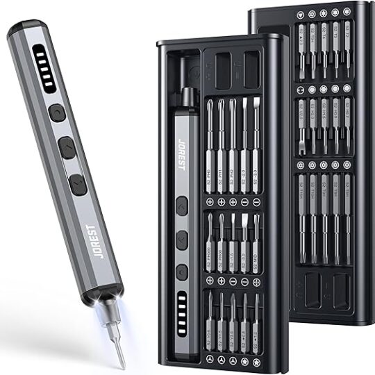
Selecting a Bit: Choose the correct bit size and type for the screw. Insert it into the magnetic sleeve at the end of the handle.
-
Adjusting Torque: Rotate the torque adjustment collar on the handle.
-
Lower Numbers (e.g., 1-3): Lower torque for tiny, delicate screws (e.g., in glasses or watches).
-
Higher Numbers (e.g., 4-6): Higher torque for larger screws (e.g., in laptops or console controllers).
-
-
Using the Swivel Top: Place the palm of your hand on the top cap and apply gentle downward pressure. Rotate your hand to turn the driver quickly for removing screws.
-
For Precision Work: Grip the knurled handle with your fingers for fine, controlled turning when installing screws.
-
Using Extensions: Attach the included extension bar to access screws in deep or recessed holes.
Quick View
Wishlist
Compare
Add to cart-
Selecting a Bit: Choose the correct bit size and type for the screw. Insert it into the magnetic sleeve at the end of the handle.
-
Adjusting Torque: Rotate the torque adjustment collar on the handle.
-
Lower Numbers (e.g., 1-3): Lower torque for tiny, delicate screws (e.g., in glasses or watches).
-
Higher Numbers (e.g., 4-6): Higher torque for larger screws (e.g., in laptops or console controllers).
-
-
Using the Swivel Top: Place the palm of your hand on the top cap and apply gentle downward pressure. Rotate your hand to turn the driver quickly for removing screws.
-
For Precision Work: Grip the knurled handle with your fingers for fine, controlled turning when installing screws.
-
Using Extensions: Attach the included extension bar to access screws in deep or recessed holes.
-
-
-
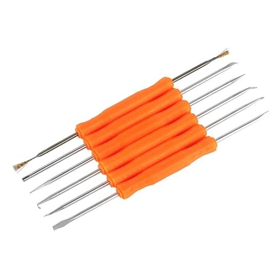
Model: Jakemy JM-Z01
-
Type: 6-in-1 soldering repair assist tools kit
-
Material: Stainless steel with insulated handles
-
Included Tools (Examples):
-
Scraper tool
-
Cleaning tool
-
Pointed tool
-
Flat tool
-
Fork tool
-
Component adjuster tool
-
-
Applications: Soldering, desoldering, PCB repair, mobile phone maintenance, electronics DIY
Quick View
Wishlist
Compare
Add to cart-
Model: Jakemy JM-Z01
-
Type: 6-in-1 soldering repair assist tools kit
-
Material: Stainless steel with insulated handles
-
Included Tools (Examples):
-
Scraper tool
-
Cleaning tool
-
Pointed tool
-
Flat tool
-
Fork tool
-
Component adjuster tool
-
-
Applications: Soldering, desoldering, PCB repair, mobile phone maintenance, electronics DIY
-
-
-
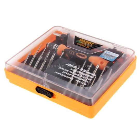
Brand: JAKEMY
-
Model: JM-8133
-
Total Tools: 45-in-1 set
-
Bit Material: Chrome-Vanadium (CR-V) steel
-
Handle Material: PP + TPR, ergonomic and non-slip
-
Accessories:
-
Extension bar (130mm)
-
Long-tip tweezers
-
Magnetic screwdriver handle
-
-
Bit Types Included:
-
Torx: T2, T4, T5, T8, T10
-
Slotted: 1.0, 1.5, 2.0
-
Phillips: 1.0, 1.5, 2.5, 3.5
-
Hex: H3.0, H4.0
-
Tri-wing: 0.8, 2.5
-
Triangle: 2.3
-
U-shape: U2.6
-
Pentalobe: 0.8, 1.2
-
Quick View
Wishlist
Compare
Add to cart-
Brand: JAKEMY
-
Model: JM-8133
-
Total Tools: 45-in-1 set
-
Bit Material: Chrome-Vanadium (CR-V) steel
-
Handle Material: PP + TPR, ergonomic and non-slip
-
Accessories:
-
Extension bar (130mm)
-
Long-tip tweezers
-
Magnetic screwdriver handle
-
-
Bit Types Included:
-
Torx: T2, T4, T5, T8, T10
-
Slotted: 1.0, 1.5, 2.0
-
Phillips: 1.0, 1.5, 2.5, 3.5
-
Hex: H3.0, H4.0
-
Tri-wing: 0.8, 2.5
-
Triangle: 2.3
-
U-shape: U2.6
-
Pentalobe: 0.8, 1.2
-
-


